Define PLC I/O Tags
Once we finished defining our PLC, we need to start adding our tags.
1. From Stream Explorer, Select Tags and click the Add button  .
.

2. In Tag Editor, enter the following:
Select Group comb box, and select <Edit..> from the end of the list.
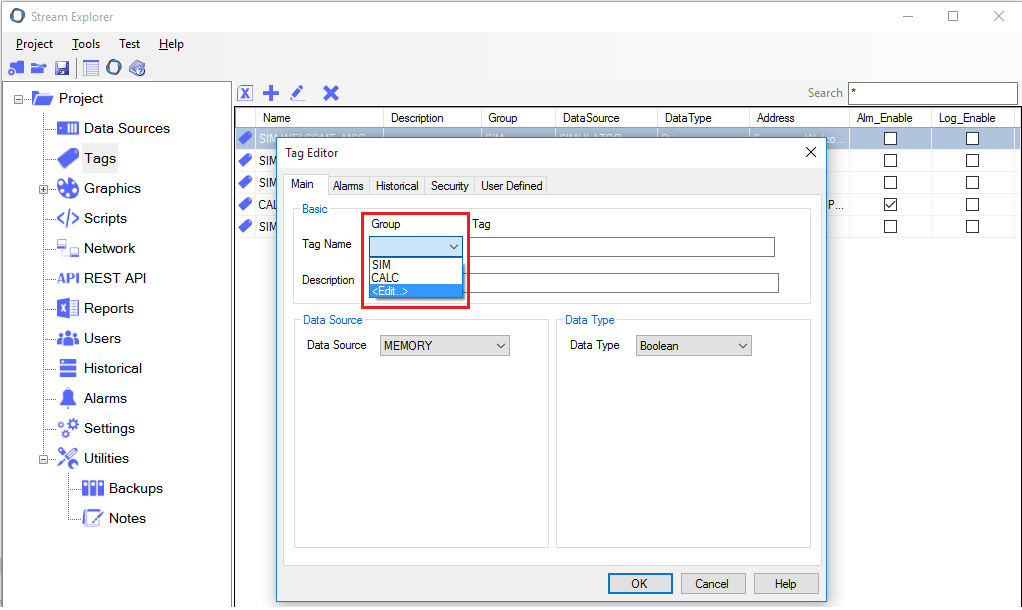
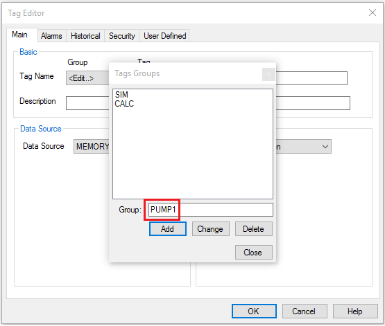
3. Tag Groups window will appear. You can add/edit/delete groups from this window.
- Enter the name "PUMP1", and click Add.
4. Enter the following details for this tag:
- Group: PUMP1
- Tag: CMD
- Data Source: PLC1
- Data Type: Boolean
- Modbus Address: 0;1 (0 means coils and 1 means the first coil). Note the semi-column separator ";".
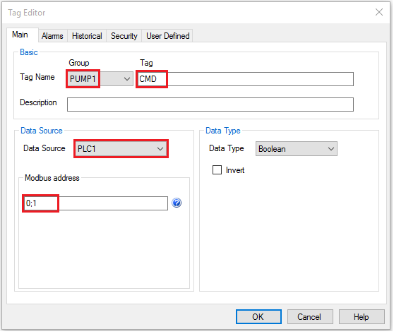
Note: Tags in Stream SCADA has the following format: "Group.Tag". In our example, the full tag name is PUMP1.CMD (Separated by dot).
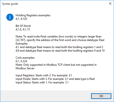
5. You can quickly check the Syntax guide to review the correct addressing format by clicking the  icon beside the Modbus address field.
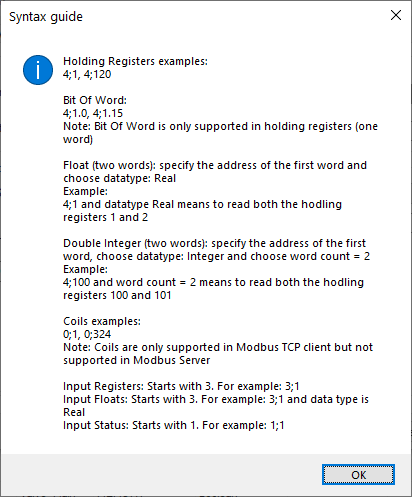
6. To complete this tutorial, you need to add the following tags. Repeat the previous steps to add the following tags list:
|
Tag Name |
Data Source |
Modbus address |
Data Type |
Description |
|
PUMP1.CMD |
PLC1 |
0;1 |
Boolean |
Pump 1 Command (Start/Stop) |
|
PUMP1.STATUS |
PLC1 |
0;2 |
Boolean |
Pump 1 Feedback status (Running/Stopped) |
|
PUMP1.TRIP |
PLC1 |
0;3 |
Boolean |
Pump 1 Tripped |
|
PUMP1.RUNTIME |
PLC1 |
4;1 |
Integer |
Pump 1 Runtime in minutes |
|
PUMP1.SPEED |
PLC1 |
4;10 |
Real |
Pump 1 Speed |
Note: As you see in the table above, the data type of PUMP1.SPEED tag is Real. This means that it needs two registers (two words). Specifying the address 4;10 means that both 4;10 and 4;11 will be read together to get the value of pump speed.
