Modbus TCP
Stream SCADA can communicate to PLC and other devices that support Modbus TCP communication. In this case, Stream SCADA acts as the Modbus TCP Client and the PLC is the Modbus TCP Server.
From Stream Explorer, select Data Sources and click on the Add button.
Main Tab:
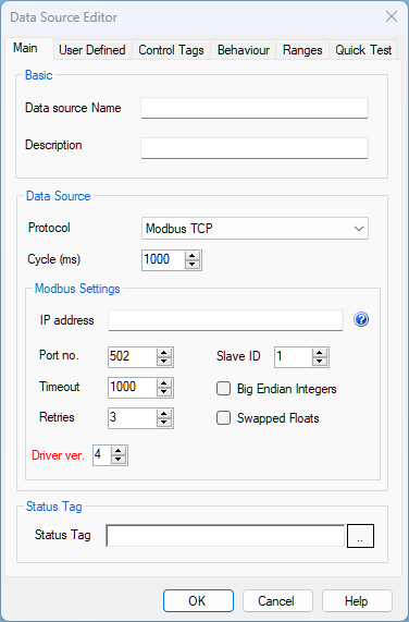
- Name: Unique name for the data source.
- Description: Optional information about the data source.
- Protocol: Selecting Modbus TCP means that Stream SCADA is Modbus TCP client that will initiate communications with a Modbus TCP Server (e.g. a PLC).
- Cycle: This is the scan rate for this data source.
- IP address: Type here the IP address of the Modbus Server device (e.g. the PLC).
Note: If you have more than one IP address (redundant), type them separated with semi column. Example: 10.10.10.1;10.10.10.2
- Port No.: Device port number. The default for Modbus is 502.
- Slave ID: Each Modbus device (Server or Slave) in a network is assigned a unique unit address from 1 to 247.
- Timeout: Configures operation or socket time-out
- Retry: Configures the automatic retry setting. A value of 0 disables any automatic retries.
- Big Indian Integers: This option is required to read data correctly from a big-indian device.
- Swapped Floats: This option is required to read data correctly in some cases (Words order need to be swapped).
- Status Tag: Select or type a Boolean tag name that will become True only when if the device comm status is healthy.
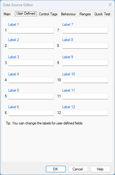
User Defined Tab:
Ranges Tab:
By default, Modbus ranges that need to be scanned are automatically determined from the defined Tags addresses. This is the default setting Generate Ranges Automatically.
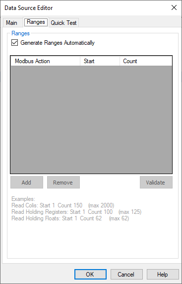
In certain situations, you may need to specify the required ranges. All Tags addresses of any defined tag should fall within one of the defined ranges. In case you want to define these ranges manually, uncheck Generate Ranges Automatically option.
In this manual definition, you can define the following Modbus actions that Stream SCADA can perform:
1. Read Coils
Performs Modbus Function Code 1 (01 hex). Define the start coil number in Start and define how many coils to be read in this scan in Count. Up to 2000 coils can be read in one scan.
2. Read Holding Registers
Performs Modbus Function Code 3 (03 hex) for integer data types (16-bit). Define the start holding register number in Start and define how many holding registers to be read in this scan in Count. Up to 125 registers can be read in one scan.
3. Read Holding Longs
Performs Modbus Function Code 3 (03 hex) for double words data types (32-bit). Define the start holding register number in Start and define how many holding double words to be read in this scan in Count. Up to 62 double words can be read in one scan.
4. Read Holding Floats
Performs Modbus Function Code 3 (03 hex) for floating data types (32-bit). Define the start holding register number in Start and define how many floats to be read in this scan in Count. Up to 62 floats can be read in one scan.
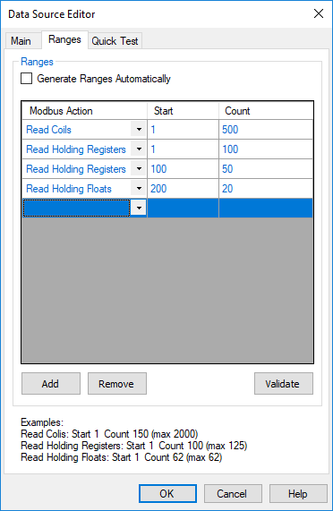
The above example instructs Stream SCADA to perform the following during runtime:
- Read Coils from 1 to 500.
- Read Holding Registers from 1 to 100.
- Read Holding Registers from 100 to 150.
- Read Floats from 200 to 220.
Note: You can copy the entire table of ranges from Excel. Simply by Ctrl+C and then Ctrl+V.
The next step is to add Tags and link them to this data source. See Modbus Addressing.